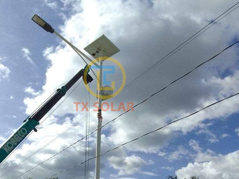
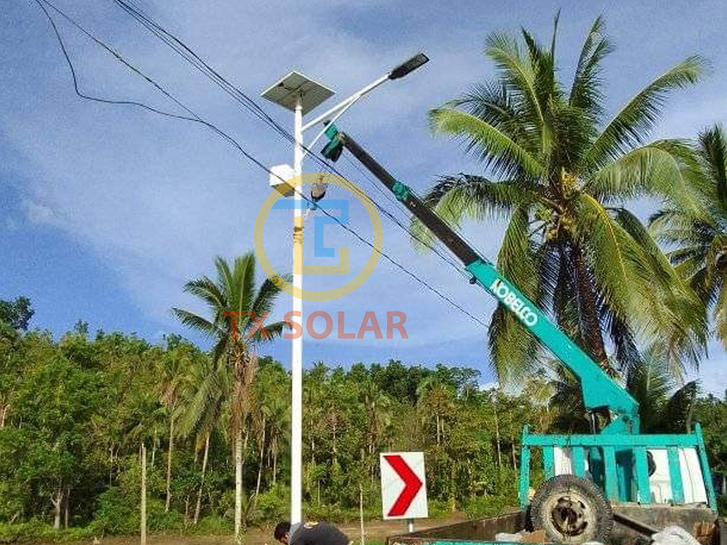
The reason why solar street lamps are so popular is that the energy used for lighting comes from solar energy, so solar lamps have the feature of zero electricity charge. What are the design details of solar street lamps? The following is an introduction to this aspect.
Design details of solar street lamp:
1) Inclination design
In order to make solar cell modules receive as much solar radiation as possible in a year, we need to select an optimal tilt angle for solar cell modules.
The discussion on the optimal inclination of solar cell modules is based on different regions.
2) Wind-resistant design
In the solar street lamp system, the wind resistance design is one of the most important issues in the structure. The wind-resistant design is mainly divided into two parts, one is the wind-resistant design of the battery module bracket, and the other is the wind-resistant design of the lamp pole.
(1) Wind resistance design of solar cell module bracket
According to the technical parameter data of the battery module manufacturer, the upwind pressure that the solar cell module can withstand is 2700Pa. If the wind resistance coefficient is selected as 27m/s (equivalent to a typhoon of magnitude 10), according to the non-viscous hydrodynamics, the wind pressure borne by the battery module is only 365Pa. Therefore, the module itself can fully withstand the wind speed of 27m/s without damage. Therefore, the key to consider in the design is the connection between the battery module bracket and the lamp pole.
In the design of general street lamp system, the connection between battery module bracket and lamp pole is designed to be fixed and connected by bolt pole.
(2) Wind resistance design of street lamp pole
The parameters of street lamps are as follows:
Battery panel inclination A=15o lamp pole height=6m
Design and select the weld width at the bottom of the lamp pole δ = 3.75mm light pole bottom outer diameter=132mm
The surface of the weld is the damaged surface of the lamp pole. The distance from the calculation point P of the resistance moment W on the failure surface of the lamp pole to the action line of the battery panel action load F on the lamp pole is
PQ = [6000+(150+6)/tan16o] × Sin16o = 1545mm=1.845m。 Therefore, the action moment of wind load on the failure surface of lamp pole M=F × 1.845。
According to the design maximum allowable wind speed of 27m/s, the basic load of 30W double-head solar street lamp panel is 480N. Considering the safety factor of 1.3, F=1.3 × 480 =624N。
Therefore, M=F × 1.545 = 949 × 1.545 = 1466N.m。
According to mathematical derivation, the resistance moment of the toroidal failure surface W=π × (3r2 δ+ 3r δ 2+ δ 3)。
In the above formula, r is the inner diameter of the ring, δ Is the width of the ring.
Resistance moment of failure surface W=π × (3r2 δ+ 3r δ 2+ δ 3)
=π × (3 × eight hundred and forty-two × 4+3 × eighty-four × 42+43)= 88768mm3
=88.768 × 10⁻⁶ m3
Stress caused by action moment of wind load on failure surface=M/W
= 1466/(88.768 × 10-6) =16.5 × 10⁶pa =16.5 Mpa<<215Mpa
Where, 215 Mpa is the bending strength of Q235 steel.
The pouring of the foundation must comply with the construction specifications for road lighting. Never cut corners and cut materials to make a very small foundation, or the center of gravity of the street lamp will be unstable, and it is easy to dump and cause safety accidents.
If the inclination angle of the solar support is designed too large, it will increase the resistance to wind. A reasonable angle should be designed without affecting the wind resistance and the conversion rate of solar light.
Therefore, as long as the diameter and thickness of the lamp pole and the weld meet the design requirements, and the foundation construction is proper, the solar module inclination is reasonable, the wind resistance of the lamp pole is no problem.
Post time: Feb-03-2023


